Types of Valve End Connections
Threaded Connections
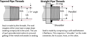
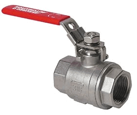
NPT - National Pipe Thread Tapered
NPT is defined by ANSI/ASME standard B1.20.1.
There are 25 sizes defined from 1/16" to 24", (see chart with sizes and dimensions) however typically valves over 4" will use flanged connections rather than threaded.
NPT threads are specified using the size in inches followed by "NPT".
example: 2" NPT
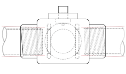
BSPT - British Standard Pipe Taper Threads
This standard is similar to NPT, where the threaded portions of the connection are tapered. The only difference is the angle of the thread flanks. The angle from root to crest on BSPT threads is 55° as opposed to 60° for NPT. It is possible for a male NPT to fit into a female BSPT, but due to the difference of the thread angle a fluid tight seal will not be made.
BSPT threads are defined by ISO 7 and/or EN 10226-1, BS 21.
BSPT threads are specified using the letter "R" followed by the size in inches. R stands for "rohr" which is german for pipe.
example: R 2 1/2"
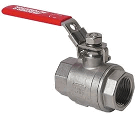
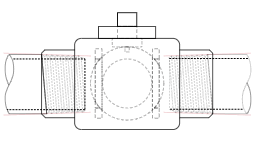
BSPP - British Standard Parallel Pipe Threads
This type of thread does NOT form a fluid tight seal like the tapered threads do. The use of a soft seal is required to do so. These threads will pull the 2 mating parts together, and compress the soft seal between flat surfaces on each component.
BSPP threads are defined by ISO 228-1:2000 (Dimensions, tolerances, and designation) and ISO 228-2:1987.
BSPP threads are specified using the letter "G" followed by the size in inches. G stands for "gas".
example: G 1/2"
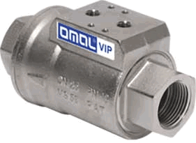

Welded, Soldered, and Glued Connections
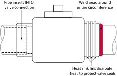
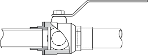
Socket Weld
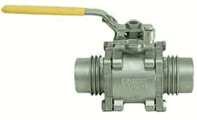
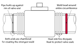
Butt Weld
Soldered (also referred to sweat)
Glue Socket
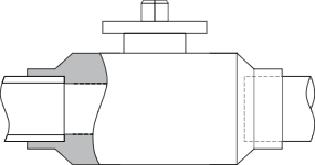
Glue socket connections are also referred to as FIP, slip-fit, friction fit, pipe end, or spigot connections. They are very simple. The inner diameter of a glue socket connection is ever so slightly larger than the outer diameter of the pipe, which simply inserts into the socket. PVC cement is used (prior to inserting) to attach PVC or CPVC valves to PVC or CPVC pipes. It is recommended to twist the pipe 1/4 turn as it is inserted. The cement actually melts the pieces together making them permanent. These connections cannot be un-done.
Flanged Connections
Most flanged end connections adhere to an industry standard. These standards define certain criteria that must be met in order to facilitate the use of products from various manufacturers.
ANSI is the American National Standards Institute. Together with the ASME (American Society of Mechanical Engineers), they have developed and published a standard for flange connections. That standard is ASME/ANSI B16.5.
There is also a European standard that is similar, but NOT THE SAME. That standard is DIN, which is an acronym for the german translation of "German Institute for Standardization." The specific standard for pipe flanges is DIN EN 1092-1. This standard is also recognized by ISO (International Standards Organization) under ISO 7005.
SAE is the Society for Automotive Engineers. They have also developed a standard for flange type connections where the flange is separate from the components that it holds together. That standard is SAE J518. This standard is also recognized by ISO under ISO 6162.
ANSI/ASME B16.5
This standard is based on using multiple bolt holes evenly distributed around a "bolt circle". There are 7 classes from 150# to 2500# with the pressure increasing as the class does. The standard includes flanges for pipe sizes from 1/2" to 24." There are a few different types of flanges
Class 150: 1/4" to 24"
Class 300: 1/4" to 24"
Class 400: 1/4" to 24"
Class 600: 1/4" to 24"
Class 900: 1/2" to 24"
Class 1500: 1/2" to 24"
Class 2500: 1/2" to 12"
These classes are referred to as "Class 150," or "150#" interchangeably.
DIN 1092-1/ISO 7005
This standard is very similar to ANSI. These flanges are referred to with a "DN" (for Diameter Nominal) followed by size in mm, followed by "PN" (for Pressure Nominal) followed by presure rating in bar. There are 19 sizes from 10 to 2000 and XX pressure classes from 2.5 to 100 bar
example: DN 100 PN 16
Round Flange Types
Both of the standards just mentioned have many different types within them. These types include different mating face styles. The most commonly used on valves are RF for "raised face" where there is a slightly raised inner ring arounf the valves port. Flat faces, counter-bore, o-ring groove, and other styles are available but uncommon in most industries.
There are also various styles that attach to pipes differently. That has no affect on the valve ends. The flanges on the valve are usually part of the valve body itself. They mate up with a matching flange that must be attached to the pipe. That is usually accomplished with welding, and less common with threading.
SAE J518
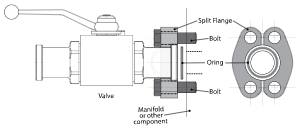
This standard is based on using 4 bolt holes located on the corners of a rectangle. There are 2 classes, Code 61 and Code 62. The flanges can be split into 2 halves known as "split flanges", or as a single piece which is called "captive."
SAE J518-1 Code 61 (ISO 6162-1): 3000 psi, 1/4" to 24"
SAE J518-2 Code 62 (ISO 6162-2): 6000 psi, 1/4" to 24"
ANSI Flanges
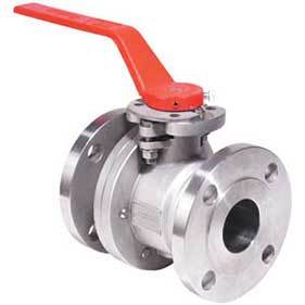
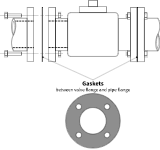
The valve has a flanges with bolt holes used to bolt it to matching flanges on the pipe. Flanged connections make removal and replacement easy. Flanged connections are common on larger valve sizes. Gaskets must be used where these flanges mate.
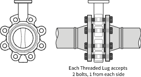
ANSI Flange (Lugged Style)
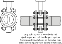
ANSI Flange (Wafer Style)
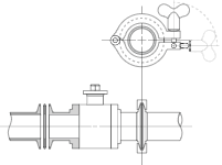
Tri-Clamp
SAE 4-bolt Flanges
Compression
Traditional Compression
This type of connection is typically found on water lines in residential plumbing. They do not require heat like soldered or welded connections making them perfect for installation in places where the use of such would be difficult or dangerous. The connection uses 2 pieces in addition to the valve and pipe. They are the ferrule (sometimes called an olive or sleeve) and a compression nut. The Compression nut is slid onto the pipe with the threads facing where the valve will be. Then the ferrule is slid onto the pipe. If the ferrule is not symmetrical, the longer side should be toward the valve. Next the pipe is inserted into the valve and the compression nut is tightened. Tightening this nut forces the ferrule into the valve stub which is tapered on the inside. Since the ferrule is made of a softer metal than the nut and valve, it gets compressed around the pipe. It also gets compresed between the valve and compression nut, forming a fluid tight seal.
Push-in
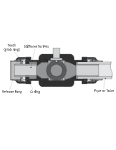
Push-to-connect connections are mainly used in residential and commercial plumbing. Originally developed for fittings such as tees, elbows, and couplings, these connections can also be found on valve ends. These innovative connection types allow quick and easy connection of the pipe(s) to the valve. There is an o-ring inside the valve port that is slightly smaller than the outer diameter of the pipe to be connected. When the pipe is pushed in, the o-ring gets stretched around the pipe and compressed between the valve body and the pipe. There is a grab-ring with teeth that dig into the pipe and prevent it from being removed. The pipe can be easily removed by pressing the release ring in which retracts the teeth of the grab-ring.
Barbed Hose Connections
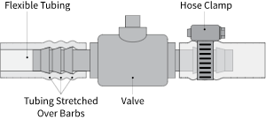
Barbed hose connections are a simple and fairly primitive way of connecting soft hose ends to a valve. They are commonly found on low presure systems including air lines for an aquarium. The valves have long end connections that have barbs on them. The hose gets stretched over them when inserted and due to their shape go on far more easily than they come off. In many case this is a sufficient connection as-is, however, a hose clamp can be used to strengthen the connection if needed.
Union/True Union
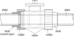
Union
Union connections employ a female threaded collar nut that threads on to a male threaded end connection of the valve. Typically union connections fasten stubs of another connection type, like welded, glue, or threaded, onto the valve. Those connections then are attached to the pipe. Once installed, the valve body can easily be removed from the pipe using the threaded union connections. This connection type allows for fast and easy removal of the valve for cleaning, replacement, or repair.
Our P2 and PTP series PVC ball valves feature true-union connections and come with both NPT female and glue socket connections. They also feature the Dual-block locking system that prevents the threaded collar nuts from loosening due to vibration.
